
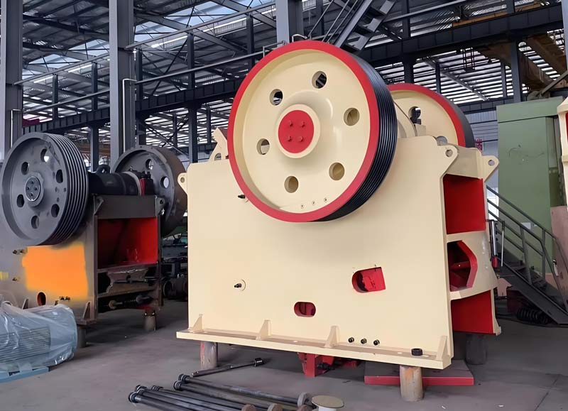
System inspection contents of roller crusher
After the roller crusher is installed, the following steps should be followed for inspection:
I. Mechanical Components
1. Remove the oil pipes from the rollers and roller supports as shown in the diagram;
2. Tighten all bolts to the specified torque using a torque wrench;
3. Check the location of the lubrication oil pipes;
4. Turn on the centralized lubrication system until grease overflows from all shaft seals;
5. Bleed the system;
6. Check the cooling water circuit;
7. Check that the monitoring devices are functioning correctly;
8. Check the system for any debris;
9. Check the hydraulic system oil level;
10. Check the gearbox oil level;
11. Check the circulating lubrication system oil level.
II. Electrical Components
1. Check the main motor rotation direction; before confirming the motor rotation direction, remove the protective cover between the rollers and bearings;
2. Check that components are correctly installed;
3. Check and adjust the motor protection relays, counters, etc.;
4. Test all measuring and control equipment;
5. Test the mechanical protection devices;
6. Test safety values (e.g., resistance to ground);
7. Measure the motor insulation resistance.
III. Single Machine and Interlocking Test Run
1. The roller crusher can only be started after a thorough inspection;
2. The roller crusher can only be started when there is no filler material between the two rollers.
IV. Individual Unit Testing
1. After completing installation and pre-testing preparations, individual unit testing can begin.
2. Start each individual unit and ensure it reaches a fault-free operating state.
3. Individual unit testing requires all adjustments to be completed and the conditions for integrated testing to be met.
V. Integrated Testing
1. Integrated testing can begin immediately after individual unit testing is completed. The interlocking procedure must be confirmed beforehand. No adjustments should be made during integrated testing.
2. Integrated testing is a rehearsal for normal operation; the entire group of equipment operates in tandem. If an individual unit fails, its downstream equipment must stop.
3. Integrated testing must ensure that all equipment starts normally according to interlocking requirements and that the control system functions correctly.
4. During integrated testing, each motor must be running. The coupling should be disconnected first.
VI. Standalone and Linkage Test Run Modes
1. Standalone Mode (Field Mode)
2. Switch to Field Mode.
3. Start the gearbox oil pump.
4. Open the cooling water valve.
5. Turn on the lubrication system heater.
6. Turn on the centralized lubrication system dry oil pump.
7. Start the main motor.
8. Turn on the hydraulic system pressurization.
9. Run the roller press and auxiliary machines under no-load for 2 hours. During these 2 hours, the following checks and adjustments must be completed. Heater: Set the heater according to the roller press ambient temperature and the following oil volume requirements. Centralized Lubrication System Oil Volume Adjustment: Disconnect all bearing housing lubrication oil pipes and wrap the oil pipes with plastic bags; check according to the instruction manual whether the oil pump is set to the specified oil volume. Start the plunger pump, and set the control system oil volume or interval time according to the oil volume in each plastic bag and the oil volume required by each bearing. Reinstall all bearing housing lubrication oil pipes and continuously run the barrel pump until oil overflows from the seal.
10. Other checks and adjustments: Check the heater, check and tighten the cooling water pipes, check the roller limit switches, and adjust the roller limit switches. The proximity switch serves as a safety protection mechanism when the roller press passes large foreign objects. The proximity switch is set to activate when the hydraulic cylinder piston has 10mm of stroke remaining. When the movable roller bearing housing contacts the limit plate, the piston rod is extended by 60mm. The switch position can be precisely set based on the above description.
VII. Adjustment of Displacement Sensor
During installation, pressurize the hydraulic cylinder to 40 bar until the movable roller bearing seat is tightly against the limit plate, then determine the roller surface clearance. At this time, adjust and set the displacement sensor output current to 4.1mA. Therefore, the zero point of the displacement sensor is established. The roller surface clearance can be confirmed by measuring the thickness of a small stone that can pass through it, and this value is entered into the control program. Set the alarm values for main bearing temperature, feed temperature, and gearbox oil temperature according to the relevant instructions. Hydraulic System Bleeding: After running the hydraulic system for 4-5 hours, bleed it again. If the hydraulic system oil level is too high, the oil tank cannot accommodate the return oil generated by the retraction of the hydraulic piston rod. Therefore, with the hydraulic piston rod in the retracted state, add oil to the high oil level in the tank.
Related Products
Inquiry
Please leave us your requirements, we will contact you soon.